Wednesday, 6 March 2013

Strength Development of Sprayed Concrete


Early strength development of sprayed concrete or shotcrete

Concrete Strength developement of shotcreteVariable requirements for early strength development have to be met, depending largely on the point of use of the sprayed concrete or mortar. A distinction is made between:
• very early strength development in the range of a few minutes to about 1 hour
• early strength development in the range of about 1 hour to max. 1 day
After that we require
of normal strength development, comparable with that of structural concrete. The strength development is influenced by the same factors:
• cement type and content
• water content
• temperatures in the concrete and the environment (substrate)
• layer thickness
• For sprayed concrete there is the added strong influence of the accelerator, which is intended to greatly increase the strength from the first few minutes to the first few hours.
Sprayed concrete or shotcrete is mainly used for stabilisation, but also frequently to grout or fill cavities. Mainly for rock and soil support and overhead spraying requirements for very early and early strength development are crucial and are generally specified.
Very early strength development
In the first few minutes after application of the sprayed concrete, the adhesive strength is decisive. Accurate dosage of the amount of air has here a great influence. It determines the rate of application (thickness). The consequence of insufficient air is insufficient concrete compaction which in its turn negatively influences final strength of the sprayed material.
Too much air produces much dust and high rebound losses. Fine cement and accelerator particles lost in the dust are important components missing for optimal strength development. Dust emission must also be avoided as much as possible for reasons of work hygiene (health protection). In any case, it is never possible to apply more sprayed concrete than the substrate is capable of absorbing, even as initial tensile force on the surface. The very early strength development determines the speed of advance and therefore the performance of the contractor .
A measurable compressive strength is obtained after about 1 hour (in special cases or in immediate stabilisation after only a few minutes). This strength development determines when heading can continue to advance. The early strength development determines the progress with tunnelling.
Final strength
Alongside the very early and early strength required specifically for sprayed concrete, there are mechanical requirements for the hardened sprayed concrete, just as there are for conventional concrete, generally after 28 days. The level of strength is based on the engineering by the design requirements. The compressive strength is measured on cores taken from the structure or from sprayed panels. Cube samples of the base concrete are sometimes used as  controls, but they cannot give meaningful results for the sprayed  concrete application because the characteristics may be changed considerably by the spraying process. The setting accelerators used and the skill of the nozzle man have a huge influence on the final strength obtained. Sprayed concrete is normally designed as a thin load-bearing skin and should therefore have ductile load-bearing properties. These can be obtained with reinforcing mesh, but the use of fibres for sprayed concrete and mortar reinforcement is ideal for flexible forming of the material. Steel-fibre-reinforced sprayed concrete is an extremely high-performance, load-bearing material.
The properties of the sprayed concrete are tested on samples taken directly from the structure or from panels sprayed parallel to the application under conditions of maximum similarity and then taken for sampling without destroying the structure. Sprayed panels with defined dimensions are also used for the plate test to determine the tensile strengths and the ductilty of the reinforced sprayed concrete.

Sand and mortar

Sand Cement Mortar
Mortar is an intimate mixture of binding material, fine aggregate and water. When water is added to the dry mixture of binding material and the inert material, binding material develops the property that binds not only the inert material but also the surrounding stones and bricks. If the cement is the binding material, then the mortar is known as cement mortar. Other mortars commonly used are lime mortar and mud mortar. The inert material used is sand. In this chapter, first an introduction is given to the inert material sand and then the proportioning, mixing, curing, properties and uses of different mortars is explained. At the end of the chapter various tests conducted on mortars is presented.
Sand is a natural product which is obtained as river sand, nalla sand and pit sand. However sea sand should not be used for the following reasons:
1. It contains salt and hence structure will remain damp. The mortar is affected by efflorescence and blisters appear.
2. It contains shells and other organic matter, which decompose after some time, reducing the life of the mortar.
Sand may be obtained artificially by crushing hard stones. Usually artificial sand is obtained as a by-product while crushing stones to get jelly (coarse aggregate). Sand is used in mortar and concrete for the following purpose:
1. It sub-divides the paste of binding material into thin films and allows it to adhere and spread.
2. It fills up the gap between the building blocks and spreads the binding material.
3. It adds to the density of the mortar.
4. It prevents the shrinkage of the cementing material.
5. It allows carbon dioxide from the atmosphere to reach some depth and thereby improve setting power.
6. The cost of cementing material per unit volume is reduced as this low cost material increases the volume of mortar.
7. Silica of sand contributes to formation of silicates resulting into the hardened mass.
The properties of good sand are:
1. It should be chemically inert.
2. It should be free from organic or vegetable matter.
3. It should be free from salt.
4. It should contain sharp, angular and coarse grains.
5. It should be well graded.
6. It should be hard.

High-tech concrete technology has a famous past

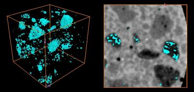
X-ray microtomograph (left) shows pores (blue) that remain within lightweight aggregates (LWAs) after water has migrated from the pre-wetted materials during the first day of hydration. In the two-dimensional image (right), the emptied pores are superimposed over the original microstructure (hydrating cement paste is white, sand is light grey, and LWA is dark grey), illustrating the detailed pore structure of LWA particles.
In the business of concrete making, what's old—even ancient—is new again. Almost 1,900 years ago, the Romans built what continues to be the world's largest unreinforced solid concrete dome in the world—the Pantheon. The secret, probably unknown to the Emperor Hadrian's engineers at the time, was that the lightweight concrete used to build the dome had set and hardened from the inside out. This internal curing process enhanced the material's strength,durability,resistance to cracking, and other properties so that the Pantheon continues to be used for special events to this day.

But it is only within the last decade or so that internally cured concrete has begun to have an impact on modern world infrastructure. Increasingly, internally cured concrete is being used in the construction of bridge decks, pavements, parking structures, water tanks, and railway yards, according to a review* of the current status of the new (or old) concrete technology just published by the National Institute of Standards and Technology (NIST).
The virtues of internally cured concrete stem from substituting light-weight, pre-wetted absorbent materials for some of the sand and/or coarse aggregates (stones) that are mixed with cement to make conventional concrete. Dispersed throughout the mixture, the water-filled lightweight aggregates serve as reservoirs that release water on an as-needed basis to nearby hydrating cement particles.
According to one study cited in the review, bridge decks made with internally cured, high-performance concrete were estimated to have a service life of 63 years, as compared with 22 years for conventional concrete and 40 years for high-performance concrete without internal curing.
"As with many new technologies, the path from research to practice has been a slow one, but as of 2010, hundreds of thousands of cubic meters" of the lighter and more durable material have been successfully used in U.S. construction, write the report's co-authors, NIST chemical engineer Dale Bentz and Jason Weiss, Purdue University civil engineering professor.
Compared with conventional varieties, internally cured concrete increases the cost of a project by 10 to 12 percent, Bentz and Weiss estimate on the basis of bridge-building projects in New York and Indiana. The increased front-end cost, they write, must be evaluated against the reduced risk of cracking, better protection against salt damage, and other improved properties that "should contribute to a more durable structure that has a longer life and lower life-cycle costs," they write. "Further, this could have substantial benefits in a reduced disruption to the traveling public, generally producing a more sustainable solution."
The 82-page report summarizes the current practice and theory of internal curing, reviews project experiences and material performance in the field, and describes opportunities for research that could lead to enhancements in the material.

'Green' research at Louisiana Tech results in new geopolymer concrete technology


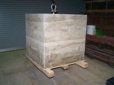
This is a 5,000 lb. geopolymer concrete block cast using fly ash.

Dr. Erez Allouche, assistant professor of civil engineering at Louisiana Tech University and associate director of the Trenchless Technology Center, is conducting innovative research on geopolymer concrete and providing ways to use a waste byproduct from coal fired power plants and help curb carbon dioxide emissions. Inorganic polymer concrete (geopolymer) is an emerging class of cementitious materials that utilize "fly ash",one of the most abundant industrial by-products on earth, as a substitute for Portland cement, the most widely produced man-made material on earth.
Portland cement production is a major contributor to CO2 emissions as an estimated five to eight percent of all human-generated atmospheric COworldwide comes from the concrete industry. Production of Portland cement is currently toping 2.6 billion tons per year worldwide and growing at 5 percent annually.
Geopolymer concrete has the potential to substantially curb COemissions, produce a more durable infrastructure capable of design life measured in hundreds of years instead of tens, conserve hundreds of thousands of acres currently used for disposal of coal combustion products, and protect aquifers and surface bodies of fresh water via the elimination of fly ash disposal sites.
In comparison to ordinary Portland cement (OPC), geopolymer concrete (GPC) features greater corrosion resistance, substantially higher fire resistance (up to 2400° F), high compressive and tensile strengths, a rapid strength gain, and lower shrinkage.
Perhaps Geopolymer concrete's greatest appeal is its life cycle greenhouse gas reduction potential; as much as 90% when compared with OPC.
This technology, along with other important research being conducted to meet future energy needs, will be highlighted at Louisiana Tech will feature this technology at its Energy Systems Conference on November 5 at the Technology Transfer Center in Shreveport.

Barrette Pile – An Advanced Foundation Technology


Barrette pile is a type of drilled and cast-in-place pile, the distinctive characters of which are the shape and way of drilling. Grab-bucket or Hydrofraise type drilling tools are used for barrette pile construction. The size of these tools determines that of the piles.
The simplest piles are made with one stroke of a standard size grab-bucket (or hydrofraise cutting drums). The sizes are :
§  width : 0.52, 0.62, 0.82, 1.02, 1.22, 1.52 m
§  length : 1.80, 2.20, 2.70, 3.0 m
Starting from these dimensions, bigger or more rigid piles can be formed :
bars, crosses, H shaped piles, T shaped piles…

The methods of calculation and measurement for barrettes are the same as those for drilled and cast-in-place circular piles.
METHOD OF CARRYING OUT THE WORKS
Classically, it includes 3 stages :
1. drilling,
2. putting the reinforcements in place,
3. concreting.
The drilling is generally done under a bentonitic slurry, like a classical diaphragm wall. Often, when the working platform is poor, simplified guide walls are used.
After desanding the drilling slurry, the reinforcement cage is lowered into the trench.
Concreting is done in the usual way with a tremie pipe. Depending on the size of the pile, several pipes may have to be used.
ADVANTAGES OF MULTIFORM STRIP PILES
Due to their shape, the strip piles have several advantages :
§  resistance to horizontal stress and to bending moments better than circular piles of the same section,
§  easy adjustment to structures, so that one single pile is sufficient under each column or bearing unit,
§  better mobilisation of lateral friction than a circular pile of the same section, because of a larger perimeter.
The preferential application field is that of high bearing capacities : from 5 000 kN upwards. The ability to enlarge their area easily makes their possibilities almost limitless.
QUALITY CONTROL
During the accomplishment of the work, the following are checked successively :
§  the quality of the slurry, the verticality and the depth of the borehole,
§  the position of the reinforcements,
§  the volume of concrete at each level.
After the concrete has set, a quality control very often carried out, is to inspect the continuity of the concrete by means of a sonic control. For this, 4 or more pipes are inserted into the reinforcement. Not destructive, this type of control is generally very exact and reliable.
LOADING TESTS
The development of pre-stressed tiebacks has permitted high capacity loading tests at relatively acceptable costs. The test took place on a half-size strip-pile ie. 2.20 X 0.62 m. The load was mobilised by 4 pre-stressed tie-backs 18 T 15 capable of 1 764 t at breaking point.
The maximum load applied was equal to 1.5 time the working load and the stress in the concrete was 7 MPa. The vibrating wire cells used to monitor the distribution of the stresses show that most of the load was taken up by pile toe.